
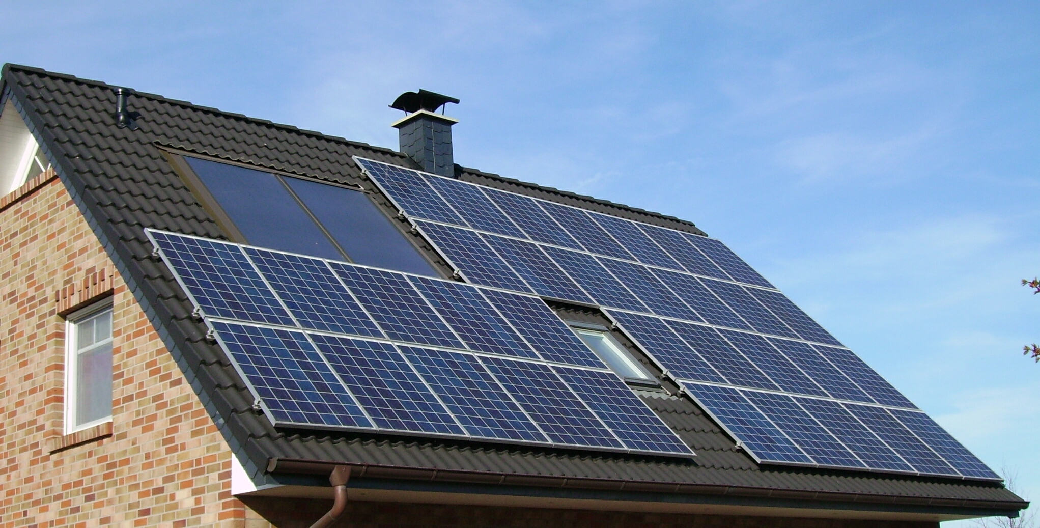
On-Roof Rail Mounting
On-roof rail mounting is the most common method used for residential installations on pitched roofs in Poland. Aluminium rails are fixed to the roof structure — typically to the rafters beneath the roof covering — using roof hooks or clamps. The panels are then clamped to the rails using mid- and end-clamps.
Roof Hooks and Penetrations
For tiled roofs (ceramic or concrete), purpose-made aluminium or stainless steel roof hooks are inserted under or between tiles and bolted to the rafter. The tile is either cut to accommodate the hook or replaced with a hook-integrated tile. Each penetration point is sealed against water ingress using EPDM rubber gaskets or lead flashing.
For corrugated metal or trapezoidal sheet roofs, clamps grip the standing seam or the profile ridge without penetrating the surface, eliminating the need for separate sealing.
Rail Alignment and Spacing
Rails are installed in horizontal pairs — upper and lower — at a spacing that matches the frame structure of the chosen panel. Standard residential panels have their frame cross-members at either 1/3 or mid-span positions; the rail spacing must correspond. A typical installation uses rails approximately 100–140 cm apart vertically for a 1700 mm tall panel.
Ventilation Gap
On-roof systems leave a gap of 50–100 mm between the back of the panel and the roof surface. This gap allows air to circulate underneath the panels, removing heat and improving operating efficiency compared to a flush surface. Good airflow behind the array can reduce cell operating temperatures by several degrees, which has a measurable effect on annual yield in summer months.
The ventilation gap in on-roof systems is also important for fire safety — it allows flames to spread beneath panels in a roof fire scenario, but also allows water from fire-fighting to reach the roof surface. Building regulations vary, and installers should be aware of relevant guidance from Polish technical standards (Polskie Normy).
In-Roof Integrated Systems
In-roof mounting replaces part of the roof covering with a photovoltaic module that is designed to function as both the structural panel and the weatherproofing layer. The PV module is seated within the roofing batten system, with surrounding tiles brought up to a flashing at the module perimeter.
Structural Requirements
Because the modules integrate into the roof surface, this approach requires either a new roof or a section of existing roof to be stripped back to the batten level. The module frame connects directly to the batten structure, and the interface between module and tile must be weatherproofed by a certified flasher or by the module's own integrated flashing system.
Aesthetic Outcome
In-roof systems produce a lower profile than on-roof rail installations, which some homeowners prefer for visual reasons. In some conservation areas or historic districts in Poland, local planning authorities may require a lower-profile solution. The trade-off is reduced rear ventilation — in-roof modules run warmer than equivalent on-roof installations, which reduces conversion efficiency slightly.
Maintenance Access
Accessing wiring or replacing a single module in an in-roof system requires undoing the surrounding flashings and may involve lifting adjacent tiles. This is more involved than on-roof systems, where individual panels can be unclipped from the rail.
Flat-Roof Ballasted Systems
Flat or low-pitch roofs (typically below 5°) found on garages, extensions, and some residential buildings use ballasted racking frames rather than penetrating or clamping to the roof surface. The aluminium or steel tilt frame holds the panel at an optimal tilt angle — typically 10–25° for Polish latitudes — and is weighted in place using concrete ballast blocks rather than structural anchors.
Wind Load Calculations
The design of a ballasted system depends primarily on wind uplift calculations. Polish standard PN-EN 1991-1-4 (Eurocode 1, Wind Actions) governs these calculations. At wind exposure zones applicable to residential areas, the required ballast per frame unit varies depending on panel area, frame geometry, tilt angle, and position on the roof relative to the parapet and roof edges. Edge and corner zones require more ballast than interior positions.
An incorrectly ballasted system risks frames sliding or overturning in high wind events. Professional structural assessment is necessary for systems covering more than a small number of panels on an exposed roof.
Structural Load on the Roof Deck
Ballasted installations add significant weight — concrete ballast blocks weigh 15–25 kg each, and a system of 20 panels might require 30–50 blocks distributed across the frames. The existing roof structure must be assessed to confirm it can bear the additional distributed load. For older buildings or those with flat roofs of uncertain specification, a structural engineer's assessment is advisable before installation.
Waterproofing Compatibility
Ballasted systems are placed on the existing waterproofing membrane (typically EPDM, TPO, or bitumen felt) without penetrating it. A protective layer — geotextile or rubber matting — is placed between the frame feet and the membrane to prevent abrasion and point loading. The membrane must be in good condition before installation; placing a solar array on a failing flat roof waterproofing layer creates access problems for later membrane repairs.
Structural Assessment for Pitched Roofs
A photovoltaic array adds dead load to the roof structure. Standard residential monocrystalline panels weigh approximately 11–12 kg/m². Rail systems, clamps, and wiring add another 3–5 kg/m². For a 20-panel installation covering roughly 35 m², the additional load is approximately 550–600 kg distributed across the rafter positions where roof hooks are attached.
Most residential roofs built to standard specifications can accommodate this load without structural modification. However, older buildings, roofs with reduced rafter sections, or those already carrying heavy roof tile loads should be assessed before installation. An engineering check is particularly advisable when the total panel area exceeds 40–50 m² on a single roof slope.
Snow Load Considerations in Poland
Poland's building code (based on Eurocodes with Polish national annexes) specifies snow loads by location. The southern regions — particularly mountain areas — carry significantly higher characteristic snow loads than the lowland central and western regions. For roof mounting design, the combined snow and panel dead load must remain within the structure's capacity. On steeply pitched roofs, panels often shed snow before significant accumulation occurs; on shallower pitches or in higher snow zones, accumulated snow may temporarily cover panels and affect production for days or weeks in winter.
Cable Routing and Protection
DC cables from the panels to the inverter typically run in conduit or cable trunking along the roof surface and through roof penetrations. Penetrations must be sealed with appropriate cable glands and waterproofed to prevent water ingress. UV-resistant cable rated for outdoor use (commonly rated -40°C to +90°C) is specified for the roof section. Cables must be routed to avoid abrasion against roof surfaces, edge flashings, or wind-driven movement.